BIM to 2D Drawing: A Practical 5-Step Workflow
BIM to 2D Drawing: A Practical 5-Step Workflow
A well-developed BIM model does not automatically produce a dependable set of construction drawings. Turning model information into usable 2D documentation requires deliberate decisions about views, dimensions, tags, details, sheet composition and quality control.

QUICK SUMMARY
- Goal: Turn BIM models into 2D drawings for design and construction.
- Workflow: Review model → Set views → Add dimensions → Create sheets → Check quality.
- Benefits: Reduce drawing inconsistencies and improve coordination and revision control.
1. BIM to 2D Drawing is more than exporting geometry
BIM models help design teams understand building geometry, relationships and element properties. Construction drawings serve a different purpose. They communicate specific design requirements through controlled scales, annotations, references and drawing conventions.
A floor plan may accurately reflect the model while still being incomplete as a deliverable. Doors may be missing location dimensions. Wall types may not be identified. A section may show the correct geometry without the levels and notes required by the construction team.
The practical objective of BIM to 2D Drawing is therefore not simply to produce a visual representation of a model. It is to transform model information into readable, coordinated and reviewable documentation.
Autodesk's Revit documentation treats view preparation, dimensions, tags, sheet assembly and document output as distinct steps in the documentation workflow. This is a useful reference when defining a BIM-based drawing process, regardless of the specific software being evaluated.
2. A practical five-step BIM to 2D workflow
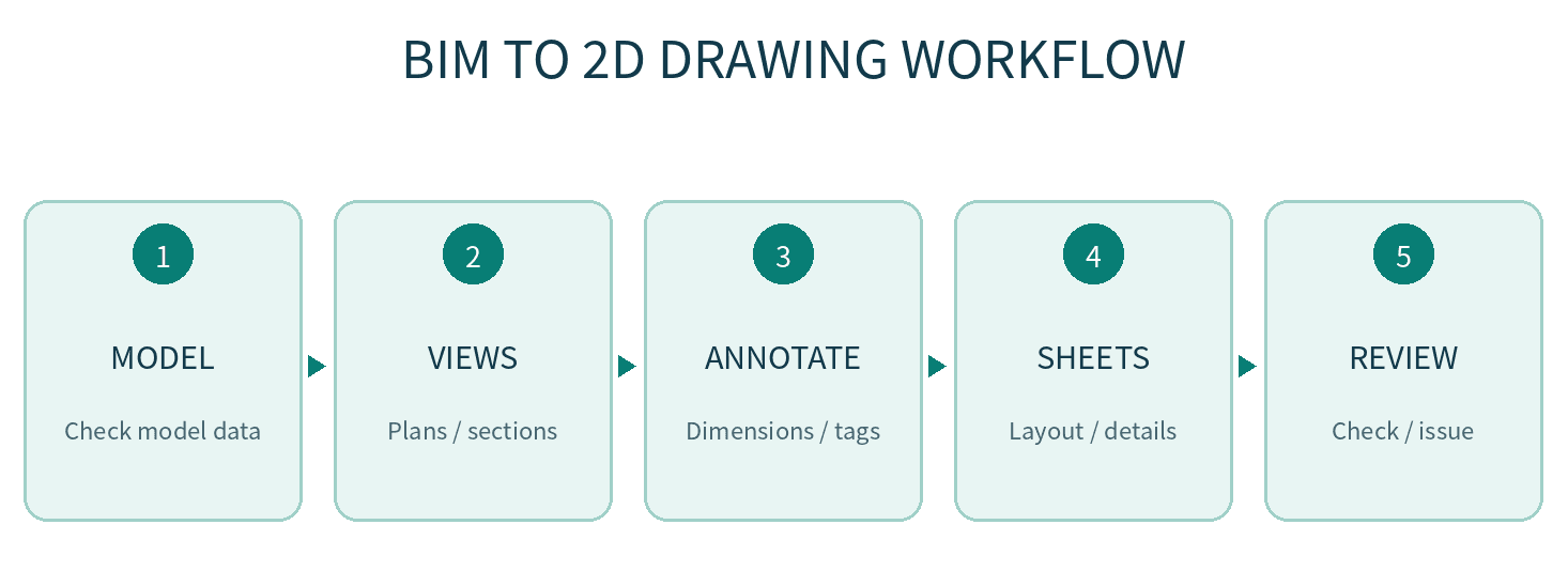
Step 1 — Verify the model before documenting it
Begin by confirming which model revision is approved for documentation. Review geometry, levels, element categories and the properties needed for annotations and schedules.
For example, a door schedule may require an element identifier, type, width, height and associated location. If those values are incomplete or inconsistent, the problem should be resolved at the data level rather than hidden through manual drawing annotations.
This distinction matters because a model can look complete while its information remains unsuitable for documentation. Visible geometry and usable BIM data are not the same thing.
Step 2 — Create views for specific documentation needs
Architectural plans, reflected ceiling plans, structural plans and sections answer different technical questions. Each requires appropriate visibility rules, cut planes, view ranges, scales and graphic conventions.
An element that does not appear in a floor plan is not necessarily missing from the model. It may simply fall outside the selected view range or be hidden by display settings. Identifying the cause before editing the model prevents unnecessary rework.
Consistent view templates are also valuable across large drawing sets. They reduce variation between views prepared by different engineers and make drawing standards easier to review.
Step 3 — Add meaningful dimensions and tags
Dimensions communicate measurements and locations. Tags identify elements or display selected model properties. Notes clarify design requirements that cannot be expressed through geometry alone.
Consider a door opening. A drawing may need the door mark, opening width, location relative to a structural grid, and a reference to a door schedule. Each item serves a different purpose.
Dimension references require particular care. An engineer should verify whether a dimension measures from an element centerline, wall face, grid line or opening edge. An apparently reasonable number can still convey the wrong construction instruction if its references are incorrect.
In Revit 2026, permanent dimensions are view-specific annotation elements. They do not automatically appear in every other view. This reinforces the need to review annotations at the drawing-view level.
Step 4 — Complete 2D details and compose sheets
Not every construction detail needs to be modeled entirely in three dimensions. Typical assemblies, material transitions, small connections and finishing requirements may be clearer when supported by 2D detailing.
Autodesk documents drafting views as a way to create details that are not directly associated with model geometry. That flexibility is useful, but it also creates a coordination responsibility when the design changes.
Drawing views can then be arranged on sheets with title blocks, drawing numbers, view references, scales and revision information. Schedules may be included where appropriate and supported by sufficiently structured model data.
Step 5 — Review the output before issuing it
The final stage is not merely exporting a PDF or DWG. It involves checking sheet completeness, dimension references, legibility, annotation consistency and revision status.
Particular attention is needed after model changes. Model-associated information and independently drafted details may respond differently to revisions. A dependable workflow makes those differences visible to the reviewer.
3. Example: What happens when a door is relocated?
Suppose door D-101 moves along a corridor wall. The new position may be obvious in the 3D model, but the documentation impact can extend well beyond the opening itself.
- Dimensions: Recheck the door's location relative to grids, walls and adjacent openings.
- Tags: Confirm that the door identifier and type information still correspond to the correct element.
- Views: Review affected plans and sections for visibility and annotation changes.
- Details: Revisit any connection or construction details affected by the new position.
- Sheets: Check references, issue information and revision descriptions.
This is why drawing productivity should not be measured only by the time needed to produce the first sheet. The effort required to manage subsequent design changes is equally important.
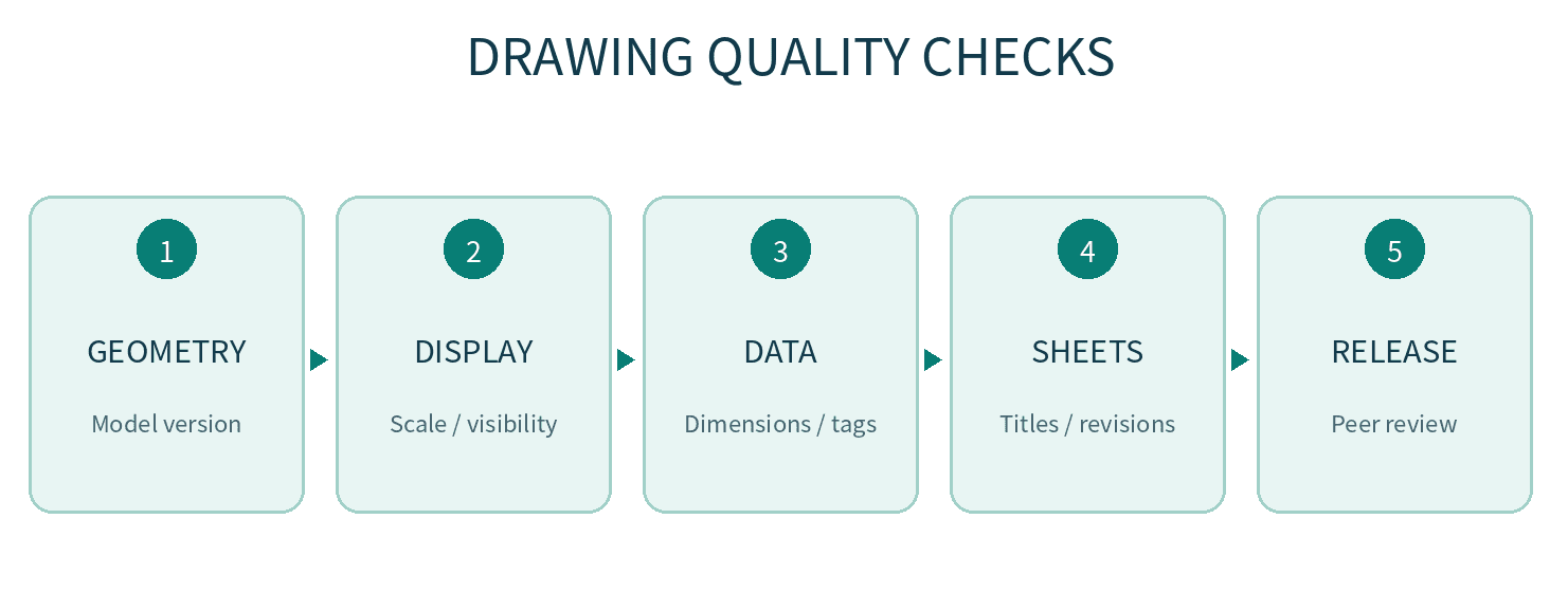
4. Drawing quality checklist for BIM teams
Area | Review question | Potential risk |
|---|---|---|
| Model | Are revisions and required properties verified? | Incorrect annotations or schedules. |
| Views | Are visibility, scale and cut settings appropriate? | Missing or misleading elements. |
| Dimensions | Are measurements tied to the intended references? | Incorrect construction positioning. |
| Tags | Do identifiers match the model data? | Element or type confusion. |
| Sheets | Are references, titles and revisions consistent? | Incomplete or outdated documentation. |
This checklist can support a basic author–checker review process. Project-specific requirements should be added for architecture, structure, MEP and any applicable client documentation standards.
5. Where VinaBIM fits into the BIM-to-drawing discussion
In many design and construction workflows, model-based coordination and conventional 2D documentation continue to coexist. Teams need both reliable model information and drawings that communicate technical decisions clearly.
BIM to 2D Drawing is a development priority within VinaBIM's product direction. The broader objective is to make BIM data more useful in practical drawing workflows.
When evaluating VinaBIM or another BIM-oriented tool, the most useful approach is to test it against representative project files and real drawing requirements. Review the specific version's capabilities for views, dimensions, tags, sheets and model properties rather than assuming that all documentation functions are available.
The goal is a repeatable, verifiable workflow: model information should remain understandable when it reaches the engineers, reviewers and construction teams who depend on the drawings.
6. Conclusion
Turning a BIM model into 2D drawings involves more than exporting files. A dependable workflow includes model review, view setup, dimensions and tags, sheet assembly, and quality checks before issue.
When evaluating tools, test them with real project documents and pay particular attention to consistency between the model and drawings after revisions.
From BIM Data to Practical Drawing Workflows
Explore VinaBIM's direction for connecting model information with everyday 2D drawing tasks in construction.
Frequently Asked Questions
Is BIM to 2D Drawing the same as exporting DWG?
No. DWG export may be one output option. A complete documentation workflow also includes views, annotations, details, sheet organization and quality checks.
Can BIM completely replace 2D drawings?
That depends on project requirements and information exchange practices. Many teams still rely on 2D deliverables alongside BIM models.
Do element tags always contain correct model data?
Not necessarily. Tag quality depends on the underlying properties, mapping rules and tool configuration. Critical values still require validation.
What should teams prioritize when selecting a tool?
Focus on drawing quality, consistency with the model, suitability for project standards and the effort needed to handle revisions.